

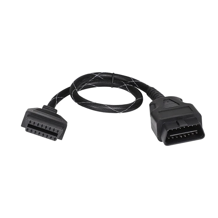
Selecting the right OBD Y cable for dual devices is a decision that directly affects diagnostic accuracy, signal reliability, and the longevity of your diagnostic tools. An OBD Y cable splits one OBD port into two simultaneous connections, allowing two diagnostic devices to operate from a single vehicle port at the same time. With so many OBD Y cable options available in the market today, knowing exactly what to evaluate before purchasing is essential for professionals and fleet technicians alike.
An OBD Y cable that is not properly matched to your devices can cause communication errors, voltage drops, and even damage sensitive diagnostic hardware. Whether you are connecting a scanner alongside a telematics module or running two monitoring systems simultaneously, choosing the correct OBD Y cable requires careful attention to pin configuration, wire gauge, shielding quality, and connector durability. This guide walks through the most critical selection criteria so you can confidently choose the right OBD Y cable for your specific dual-device application.
Understanding OBD Y Cable Pin Configuration and Compatibility
Why Pin Layout Matters for Dual Device Use
The foundation of any reliable OBD Y cable selection starts with understanding pin configuration. A standard OBD Y cable uses the 16-pin OBD-II connector layout, but not all pins are active in every OBD Y cable design. When you connect two devices through an OBD Y cable, both devices share the same power pins, ground pins, and communication bus lines. If the OBD Y cable does not correctly map each pin to both output connectors, one or both devices may fail to communicate with the vehicle ECU. Always verify that the OBD Y cable you choose supports full 16-pin passthrough for both outputs, especially if your diagnostic devices rely on manufacturer-specific pins beyond the standard CAN bus.
Protocol Support in an OBD Y Cable
Modern vehicles use several communication protocols including CAN, ISO 9141, KWP2000, and J1850. A quality OBD Y cable must support the protocols required by both connected devices without signal conflict. When two devices share the same OBD Y cable and both attempt to initialize communication simultaneously, protocol conflicts can arise if the OBD Y cable design does not include proper bus isolation or arbitration support. Before purchasing an OBD Y cable, confirm which protocols your diagnostic tools require and verify that the OBD Y cable is rated to handle those protocols without cross-interference. Choosing an OBD Y cable with protocol-aware design prevents communication collisions and protects your diagnostic equipment.
Evaluating OBD Y Cable Build Quality and Signal Integrity
Wire Gauge and Shielding in OBD Y Cable Construction
Build quality is one of the most important factors when selecting an OBD Y cable for professional use. An OBD Y cable with undersized wire gauge introduces resistance that can cause voltage drops across power lines, leading to unreliable device operation. For dual-device applications, the OBD Y cable must carry adequate current to power both devices simultaneously without thermal stress on the conductors. Look for an OBD Y cable that uses shielded twisted pair wiring on data lines, as this significantly reduces electromagnetic interference from the vehicle's ignition system, alternator, and other electrical noise sources. A well-shielded OBD Y cable ensures stable data transmission even in high-noise environments such as diesel trucks, heavy equipment, and hybrid vehicles.
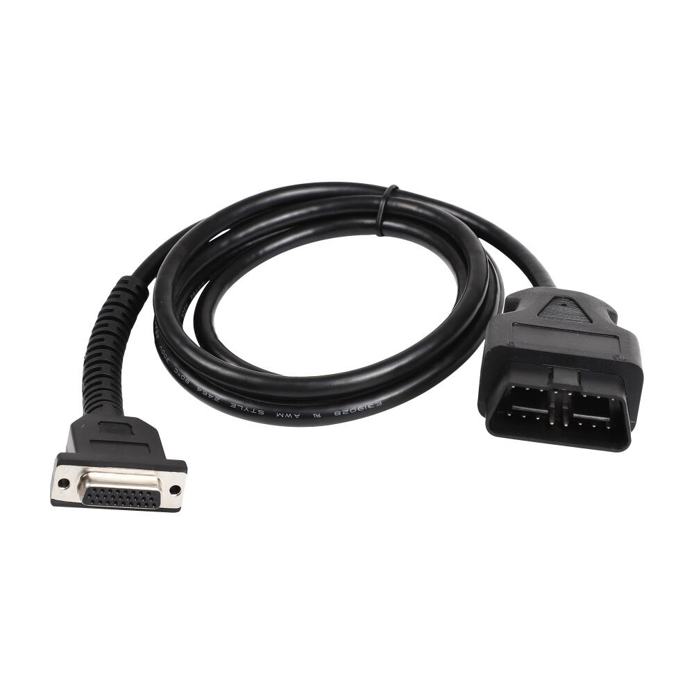
Connector Housing and Contact Durability
The physical connector quality of an OBD Y cable determines how reliably it maintains contact under real-world conditions. A robust OBD Y cable should use gold-plated or nickel-plated contacts inside the connector housing to resist oxidation and ensure consistent electrical contact over thousands of insertion cycles. The outer housing of a professional-grade OBD Y cable should be made from engineering-grade thermoplastic that resists cracking under mechanical stress and temperature variation. Poor-quality connector housings on an OBD Y cable often lead to intermittent connections, which are particularly problematic when two diagnostic sessions are running simultaneously. Inspecting the strain relief design on an OBD Y cable is also important, as this protects the cable junction from damage caused by repeated bending or accidental pulling.
Matching an OBD Y Cable to Your Dual Device Application Scenario
Scanner Plus Telematics Module Configurations
One of the most common dual-device scenarios for an OBD Y cable is pairing a handheld diagnostic scanner with a fleet telematics module. In this configuration, the OBD Y cable must allow the telematics module to maintain a continuous passive connection while the scanner initiates active diagnostic sessions on demand. Select an OBD Y cable that supports simultaneous passive and active device connections without causing the telematics module to drop its data stream. Some OBD Y cable models include a switched output port that allows one device to be prioritized when both devices attempt bus access at the same time. This type of OBD Y cable is particularly valuable in fleet management applications where uptime and continuous data logging are mission-critical requirements.
Data Logger Plus Emission Tester Use Cases
Another practical use case for an OBD Y cable involves connecting a real-time data logger alongside an emission testing device during vehicle inspection workflows. In this scenario, the OBD Y cable must handle simultaneous read requests from two devices without introducing latency or dropped frames. An OBD Y cable designed for high-frequency data applications should have low-capacitance wiring to maintain signal integrity at faster bus speeds. When selecting an OBD Y cable for this type of dual-device setup, also consider cable length, as longer OBD Y cable runs increase line capacitance and can degrade signal quality at the far end. Keeping the OBD Y cable as short as practically possible while still reaching both device mounting locations helps preserve optimal communication performance.
FAQ
Can any OBD Y cable support two active diagnostic devices at the same time?
Not every OBD Y cable is designed for two simultaneously active devices. Many basic OBD Y cable models are intended for passive plus active combinations rather than two fully active scanners. Always check the OBD Y cable specification to confirm whether it supports dual-active operation before purchasing for that use case.
What is the difference between a standard splitter and a proper OBD Y cable?
A standard splitter simply duplicates the connector without considering bus arbitration or signal isolation, while a purpose-built OBD Y cable is engineered to manage shared bus access, protect signal integrity, and support dual-device compatibility. Using a generic splitter in place of a proper OBD Y cable often leads to communication errors and potential damage to connected devices.
How do I verify that an OBD Y cable is compatible with my vehicle and devices?
To verify OBD Y cable compatibility, first confirm that the cable supports your vehicle's OBD-II protocol variant and that the pin mapping matches your diagnostic devices' requirements. Review the OBD Y cable datasheet for supported protocols, current rating, and any device pairing restrictions. Testing the OBD Y cable in a controlled environment before full deployment is always recommended when connecting critical diagnostic or telematics hardware.